
Power consumption is one of the most critical factors if you live in an RV or off-grid. Most electrical devices run on AC with a rectifier inside. So with an off-grid setup running on solar or batteries, you’ll have to use an inverter for DC to AC conversion. The rectifiers will then convert the AC back to DC in the devices. These processes are inefficient because there are losses in conversions. So it would save some watts if you run your devices directly using a DC power source. And it is possible to power a Starlink setup using DC. We will show you how to set up a Starlink DC power system to keep you online efficiently. Take a look!
Table of Contents
- Starlink Components
- What You Need To Power Starlink Using DC Power
- Starlink DC Power Conversion Without an Ethernet Adapter
- Starlink DC Power Conversion With an Ethernet Adapter
- Wrap Up
Starlink Components
Before we get started, we need to understand the components that make the Starlink system work. It has the following parts.
Starlink Dishy
The Starlink Dishy contains the modem and provides all the system’s functionality, including configurations using the Starlink app. It connects to the router using a shielded Cat5 ethernet cable.

The second-generation Starlink Dishy
Starlink Router
The AC Starlink router runs on 120V AC to broadcast the Wi-Fi signal and communicate with the Starlink Dishy. Since the dish lacks a dedicated power supply cord, it gets all its power from the ethernet plug. So it does not run on AC. But it requires significant energy, meaning you can’t plug it directly into the router. It won’t work. What you need is a PoE injector to act as the power supply.
What You Need To Power Starlink Using DC Power
The Starlink internet system can run on 12V, 24V, or 48V DC with the following components.
DC PoE (Power Over Ethernet) Injector
This component has an in-line connection with the ethernet cable to supply power to the Starlink Dishy. Technically, the device does not provide energy. Instead, it provides the mechanism to introduce or inject power(voltage) into the ethernet cable from a DC power source.
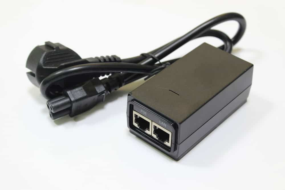
A Power Over Ethernet adapter
DC-to-DC Converter
A Starlink dish requires 48V to run. So the voltage from your batteries might not be enough. DC-to-DC converters operate like transformers because they convert DC voltage from one level to another. In this case, you need a DC-to-DC converter that can produce at least 150 watts at 48V (56V maximum power). This high input voltage range will be sufficient to supply power to the dish using the PoE. But if you have a 48V battery system, this component is not necessary.
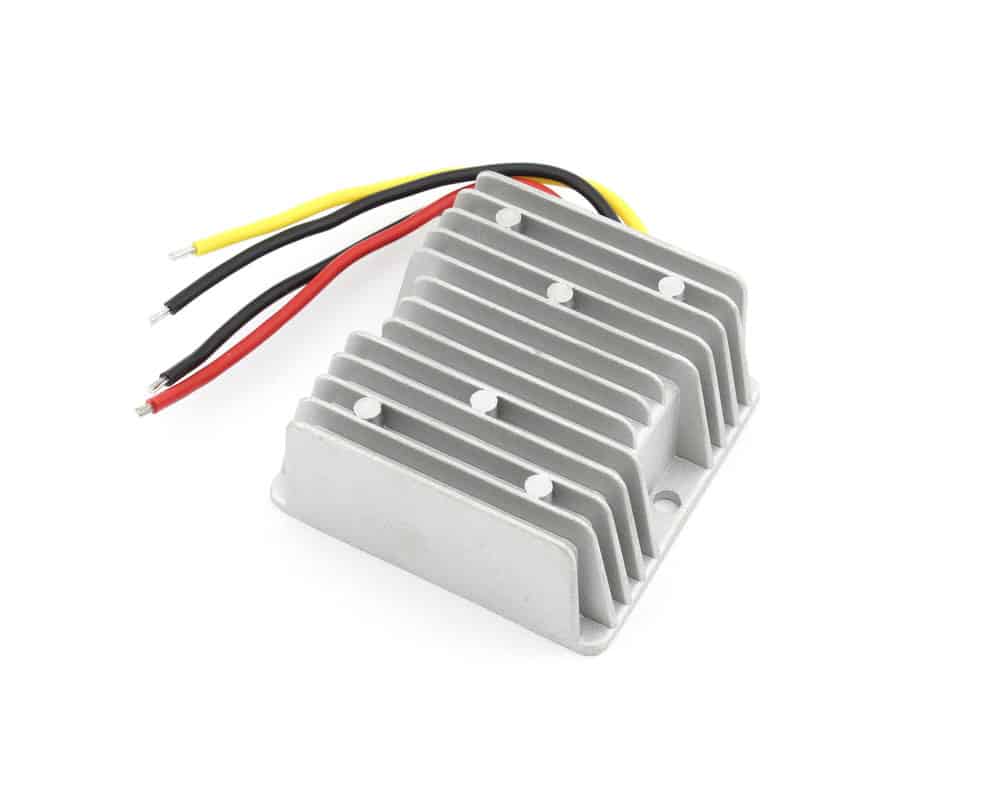
A 12V to 24V DC-to-DC converter
DC Powered Router
Lastly, get a DC router, which is not difficult to find. Most routers run on DC but use an AC plug to convert the mains power into DC. You have the option of picking a powerful router or a basic one depending on your needs.
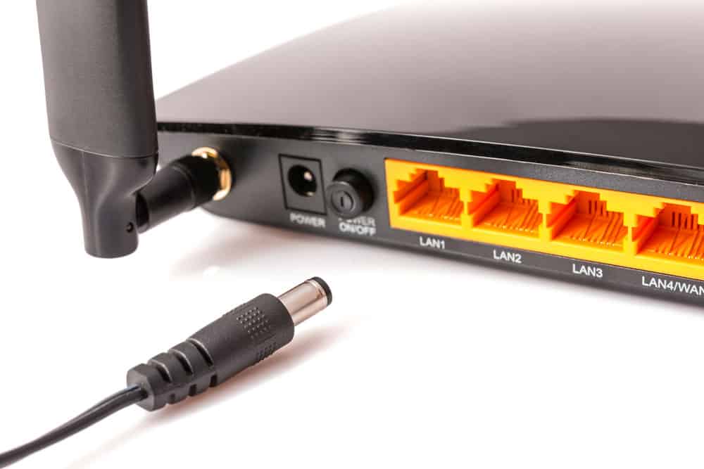
A DC connector for a router
Starlink DC Power Conversion Without an Ethernet Adapter
Let’s assume you have a 12V battery storage setup. This Starlink system will consist of a 12V input into the DC-to-DC converter, which amplifies it to 48V output power. The PoE injector takes this 48-56V input (max) and introduces it to the ethernet cable going to the dish. So you’ll have to cut the proprietary connector and replace it with an RJ45 connector in the PoE injector.
However, the wiring for this RJ45 connector will be unlike the usual straight-through or crossover (T568A/T568B) wiring. You must follow the proprietary connections for the Starlink ethernet connector you cut earlier. Let’s refer to it as the swapped connection. This swapped ethernet connector plugs into the PoE injector.

The Starlink DC conversion diagram (without an ethernet adapter)
The DC router will be on the other end of the PoE injector. So you’ll have a swapped RJ45 connector on the PoE end and a regular T568B on the router end. That’s it! The Starlink DC-powered internet system is ready to roll.
Swapped RJ45 Wiring in Starlink Connections
Let’s move a step back and look at the RJ45 connector wiring because it can be confusing. Ethernet cables contain four twisted pair wires: orange/white orange, blue/white blue, green/white green, and brown/white brown.
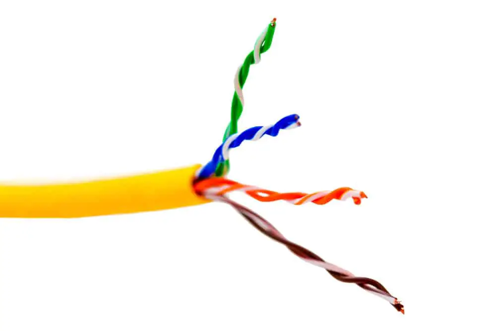
The four twisted pairs in an ethernet cable
T568A and T568B Connection
Most people are conversant with the T568A and T568B color coding. The pin color code from 1-8 in T568A follows this order.
- White Green
- Green
- White Orange
- Blue
- White Blue
- Orange
- White Brown
- Brown
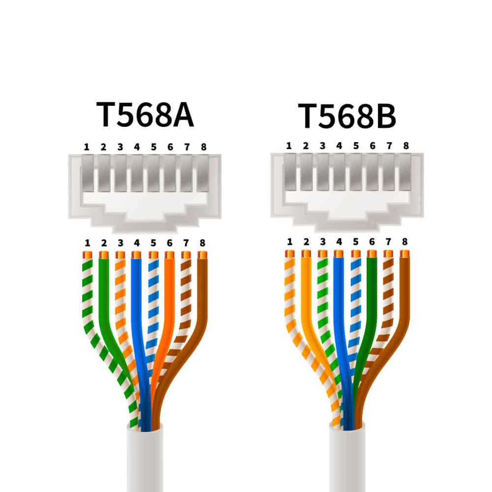
RJ45 pin assignments in T568A and T568B connection types
T568B is slightly different because it has the following order from pin one to eight.
- White orange
- Orange
- White green
- Blue
- White Blue
- Green
- White brown
- Brown
Swapped RJ45 Connection
The router/CPE connection uses the T568B wire order, but the swapped connection on both ends of the PoE is proprietary and has a unique color code. It switches the blue and green pairs in a T568B connection to inject power into them. So the order changes to the one shown below.
- White Orange
- Orange
- Blue
- White Green
- Green
- White Blue
- White Brown
- Brown
It is vital to note that Starlink uses Cat5e ethernet cables that have an extra sheath layer and a bare wire to minimize interference. So always use shielded RJ45 connectors with metals to maintain the shielding effect.
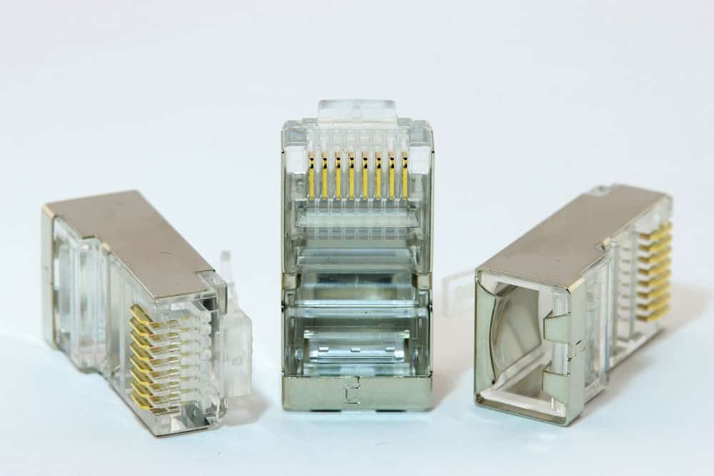
Shielded RJ45 connectors (note the metal shield housing)
And since we have covered the wire order, you might get confused because the pins 1-8 on the RJ45 connector can be facing you or away from you.
If the metal pins or contacts are facing away from you, pin one is on the left, and pin eight is on the right. But if the metal contacts are facing you, pin one is on the right and eight on the left.
Remember, you will need a crimping tool and shielded RJ45 connectors to make these connections.
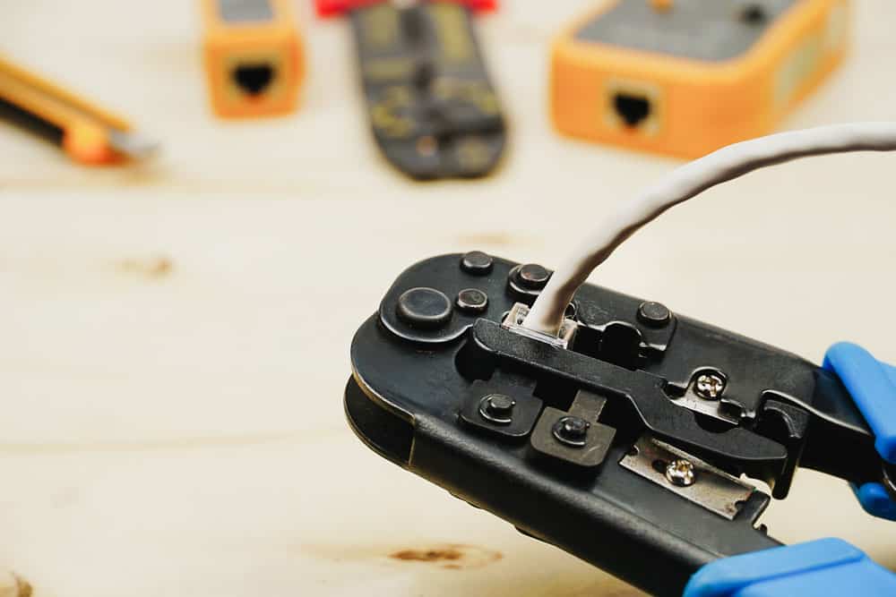
A crimping tool crimping a LAN cable into an RJ45 connector
Starlink DC Power Conversion With an Ethernet Adapter
There is another way to configure the system. It is similar to the one above but uses an ethernet adapter, eliminating the need to cut the Dishy cable. You’ll have to purchase this adapter, then place it between the Dishy and PoE injector.

The Starlink DC conversion diagram (with an ethernet adapter)
The cable from the dish will plug into the ethernet adapter directly, so there’s no need to cut it and swap the wires like in the setup above. But you’ll still have to cut the cable going into the PoE injector from the ethernet adapter and switch the blue and green pairs. Remember, this swapped connection is essential for injecting the 48V into the wires so that they reach the dish as energized data cables. The adapter has an RJ45 port that you don’t need to use.
So why go through the hassle of buying an extra component and still do the same wiring? Because you won’t cut the primary dish cable, you can return it to its stock or original operations by simply unplugging it. This setup can be ideal if you want to sell the Starlink internet system later.
Wrap Up
As you can see, it is possible to power your Starlink internet system using DC power. Although it is not an “official” way to power the devices (they run on 120V AC), you can use the steps above to create a safe conversion to DC power. The goal is to save as many watts as possible if you run on solar and battery power. So don’t do this conversion if you are a grid customer. That’s it for today. Drop a comment below if you encounter any issues or need further guidance in swapping and crimping the Cat5e cable. Cheers!